** Atari Missile Command / Crystal Castles Cabaret Combo ** |
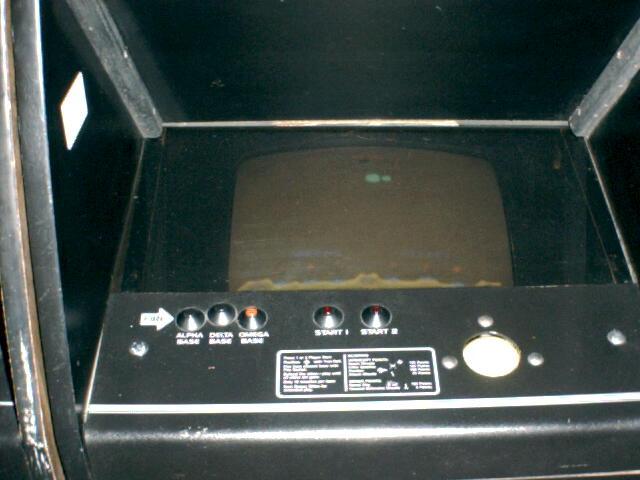
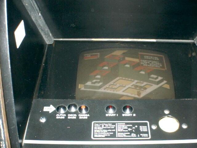
| Here is a mini (cabaret) version of
Missile Command. This one also has Crystal Castles
installed. Switching between the games is accomplished by
flicking the switch on the coin door. See below for
information on how this was accomplished. Go back to main page by clicking here. |
|
Behind the Scenes: This game was put together by Dick Millikan, a local game repair guru. I purchased it already put together from someone who had made by Dick. The concept behind this is straightforward. Inside the game, are the game boards for both Missile Command and Crystal Castles, mounted on opposite sides. The Crystal Castles board just barely fits, the edge connector pins have to be folded over to allow the back door to fit on. A groove could be routered out to allow the board to slip in a hair deeper. The inputs from the control panel, coin doors, etc are fed into both boards simulateously. The power is also fed into both boards simultaneously. This means that both games are actually running at the same time. The toggle switch on the front of the game basically just switches the input into the monitor from one particular game at a time. So, even though both games are being played, only one is being shown at a time. If you coin up and start a game, the same is being done for the other game. Inside the game, you have terminals where the control panel inputs, power inputs are fed into a post, and 2 wires leave those posts to go to both game boards. |
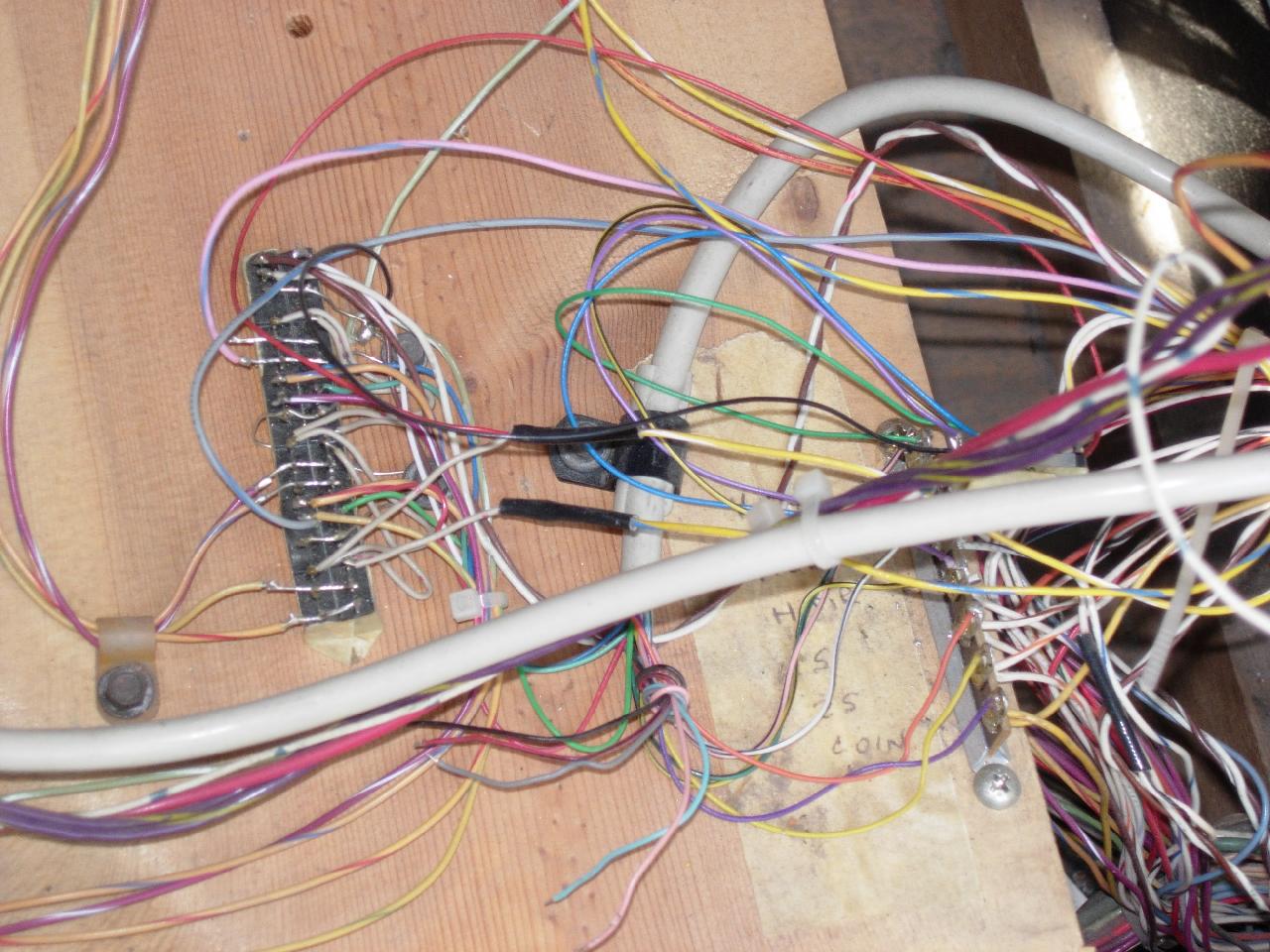
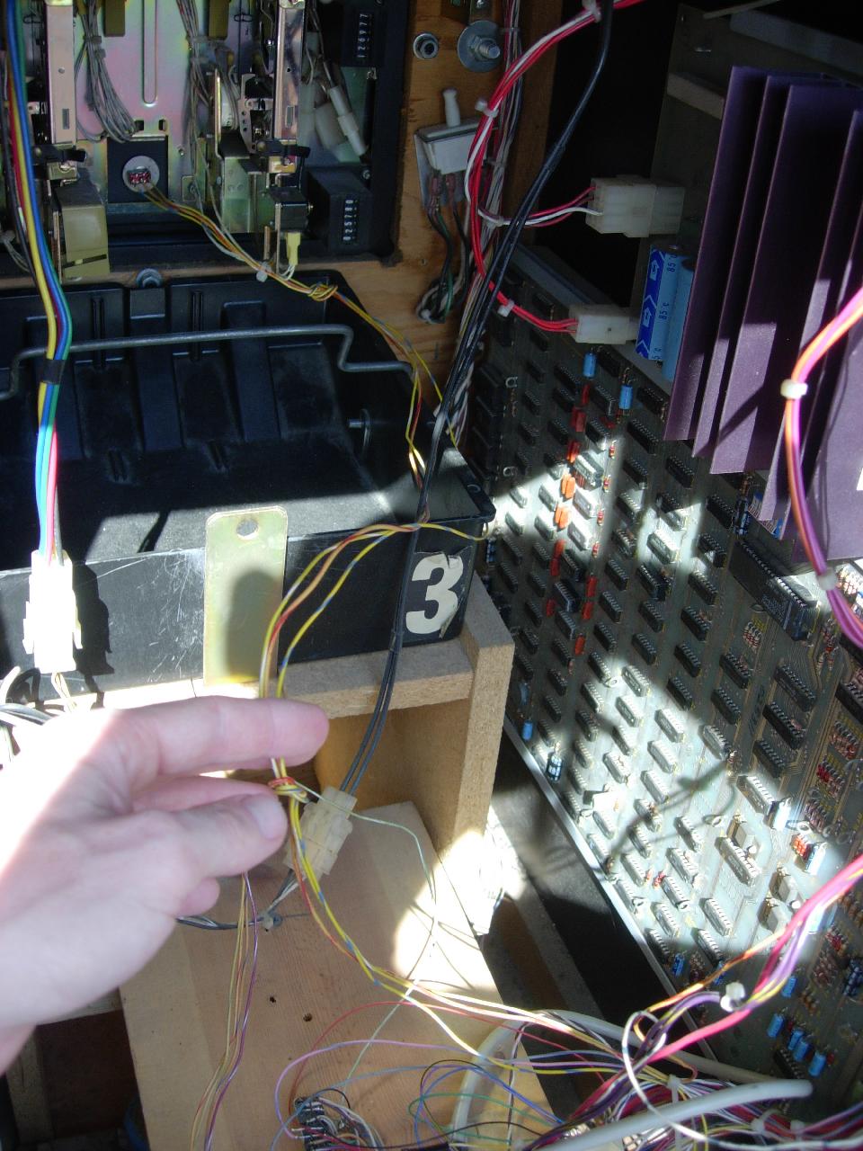
Figure 1: This picture shows the input signals
being routed to both games. Hidden from view is the relay
that controls the toggling of the inputs/outputs from the
games. There are 2 wires coming out of the relay feeding
into the bank of wires on the left side (note the 2 wires
with the black sleeves in the middle of the picture -
those are coming fromt the relay). One wire goes to the
right side of the bank, and the other goes to the left
side of the bank. The purple and yellow wires on the very
left of the picture are going to the monitor. So you can
see that the toggle switches between the left side and
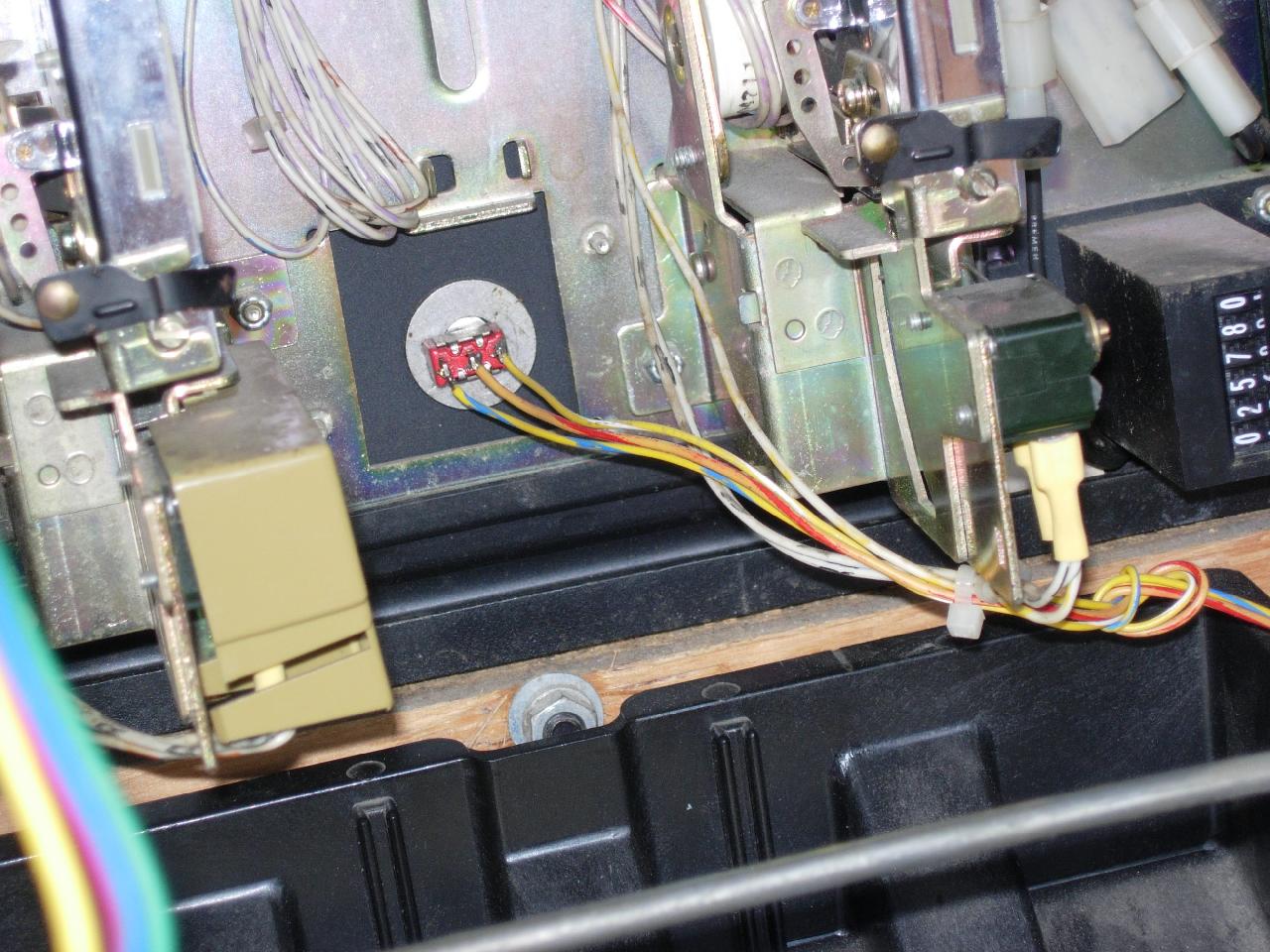
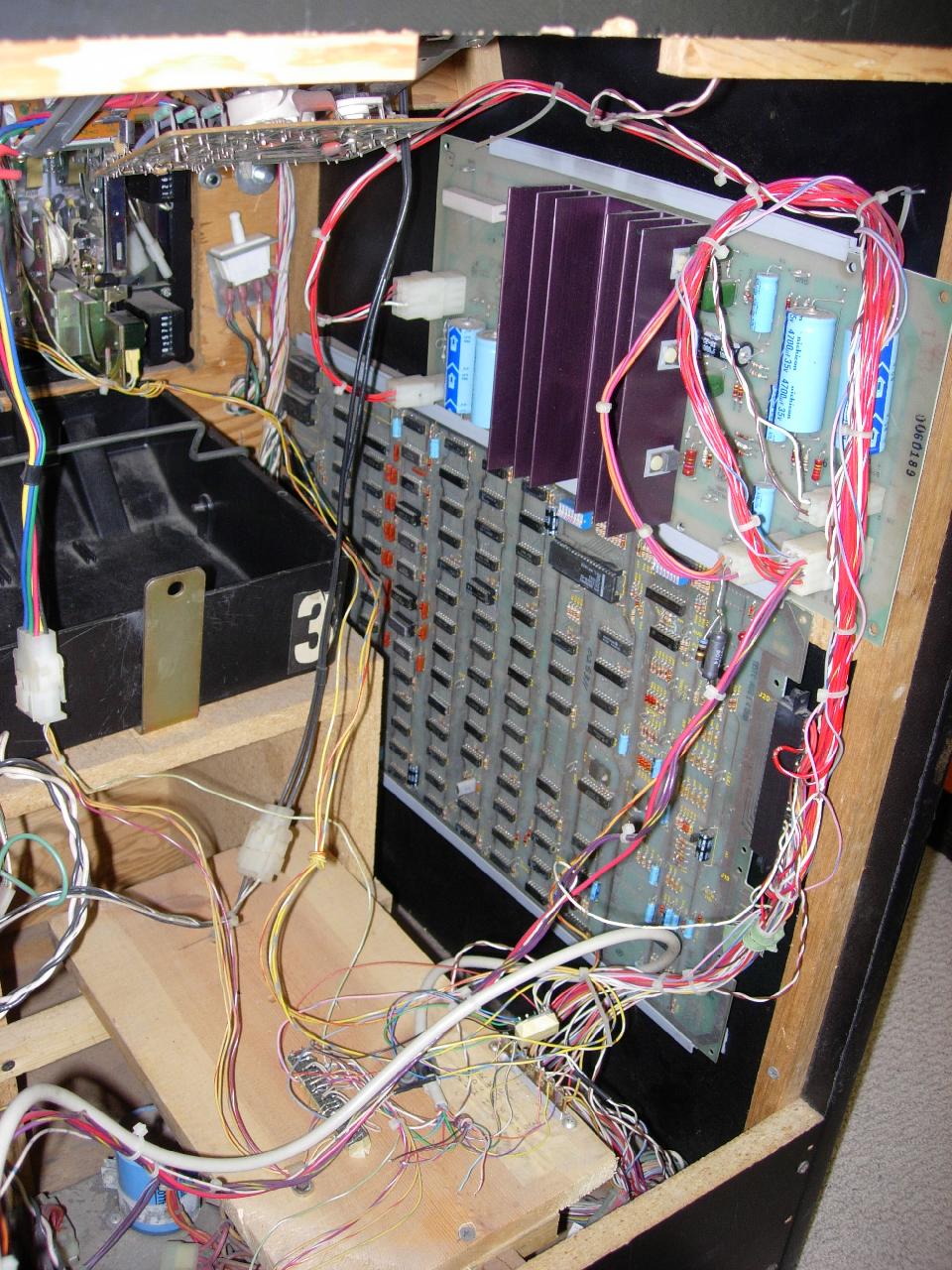
right side of the wire bank. Figure 2: Back side of the game switch inside the coin door.
One of the wires from the game toggle switch lead into a relay which controls the toggling of the monitor input from whichever game is selected. The other two go to the terminal bank on the left side (where the approriate side of the bank will get the DC power to activate the inputs and outputs for the game.
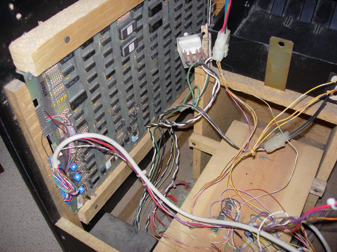
This picture shows the Crystal Castles board. Notice how little room there is between the edge connector and where the back door goes on. There are 5 wires soldered directly to the board on the top edge. If you do this project, you should use an edge connector (makes taking the board out for repair easier).
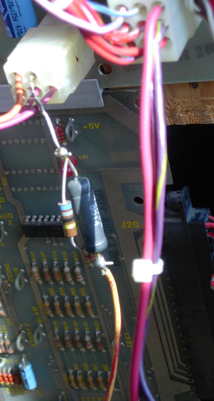
The below picture shows the ARII board which the origination of the wire that feeds DC voltage into the toggle switch which will be used to drive the relay and the banks of the I/O wiring. It's probably +5 VDC, but when I get a chance, I'll put a meter to it to confirm this. Note the resistor and diode - I'm not sure of the purpose of this.
|